I’ve always been interested in using the delay between 2 signals to determine the location of that signal. My secret goal is to have a way to locate the mosquitoes buzzing at night, so I might be able to splat them gently against the wall. The core concept I wanted to approach in this project is to show that it is possible to find the direction of a sound using 2 microphones.
The setup :
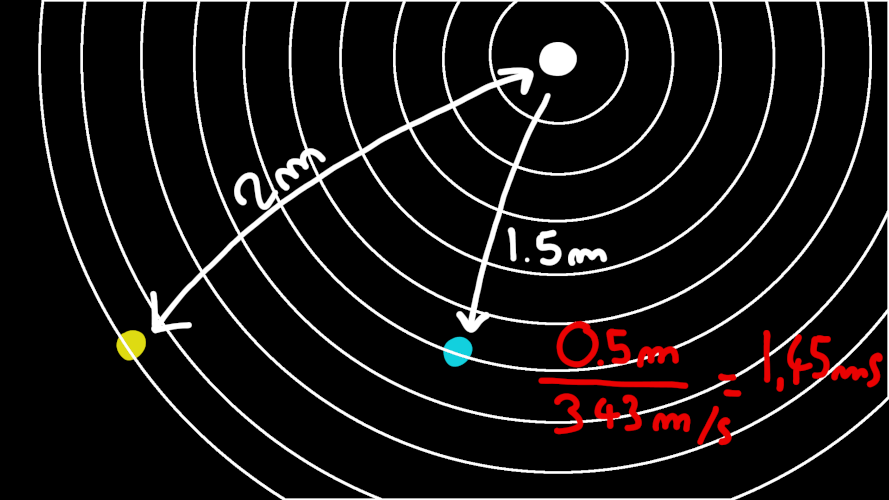
Because we know the speed of sound, it is possible to know using the time difference of arrival of the signal and the distance between the microphone where the sound comes from using simple trigonometry.
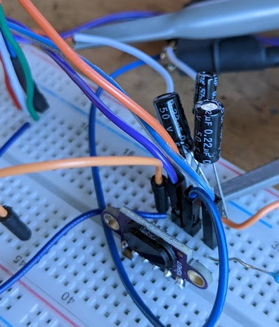
Here is a quick example using the oscilloscope.
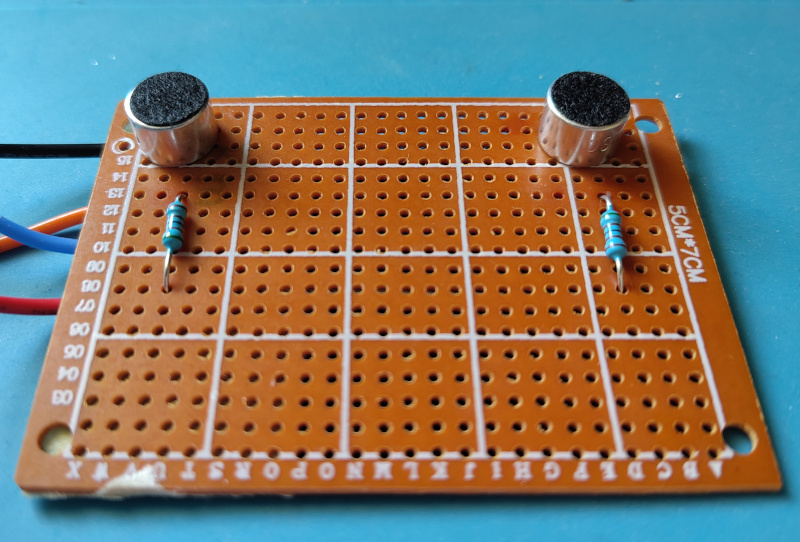
These are 2 electret microphones, and when I whistle from one side, I induce a time delay between the 2 signals of 50 micro seconds.
Building the demo
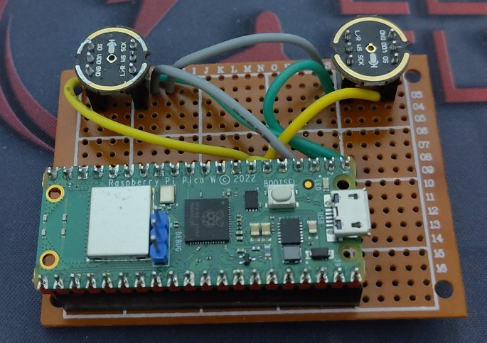
Here are 2 MEMs microphones connected to a pico using the i2s protocol.
I made a very quick and dirty code to read the values of the microphones.
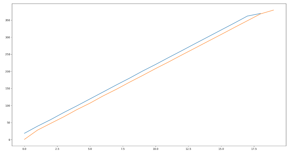
Here are 2 examples, the first shows a sample where the 2 signals have the same slope. And the offset corresponds to the delay between the microphones.
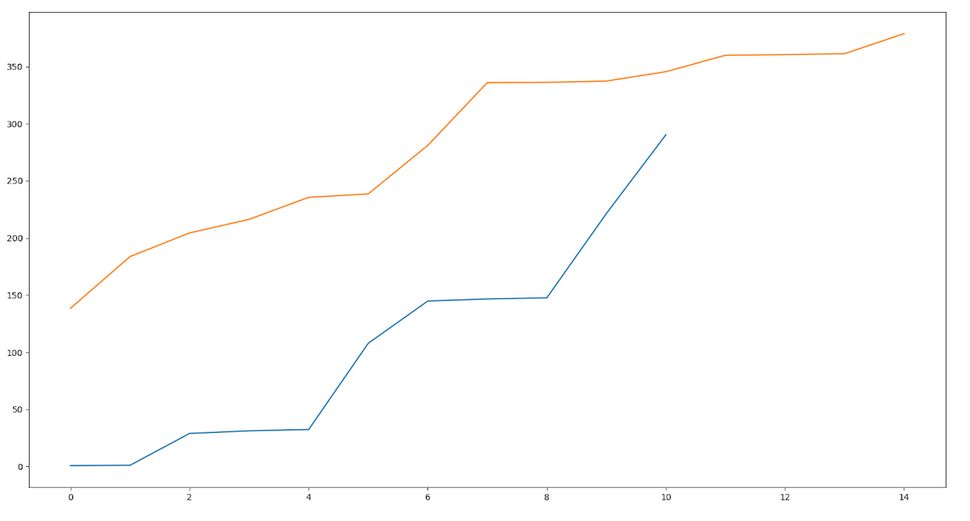
And on this graph, the slopes aren’t linear, and the 2 microphones haven’t the same slope, so this is a noisy signal to be eliminated.
Last thing left is to find whether the sound arrived first to the left microphone or the right microphone. This is looking at a crossing of the first signal and finding the nearest crossing of the same direction in the other signal.
Conclusion
This technology is used and can be used in many places. From virtual antennas, phased array antennas, radar, concerts. There are microphone arrays, and cameras which are able to overlay sound over videos, the open source project Acoular allows the user to feed audio signal and display sound location. There are opportunities such as using 2 microphones to create a left and right channel virtually by shifting the signal by the proper delay. This could also be used for geolocalisation if GPS were to become unavailable due to jamming, or within a building using frequencies above hearing range.
I hope to find novel applications using this technology to solve real life problems.
M-Bot’s purpose
When showcasing my robot, the question everyone asked was “what is it doing ?”. So here is some context on how mushrooms grow.
Mushrooms you buy in the store are the fruits of a fungus. A fungus is composed of small interconnected tubes that feed on biomass, called mycelium.
The simplest way to cultivate mushrooms is to take biomass and inoculate (i.e. : plant) it with mycelium. Wait a few months for the fungus to feed and then mushrooms will sprout.
In my case, I want to cultivate shiitake; they feed on wood, and it is a relatively easy mushroom to cultivate. The first step is to start by cutting down a tree in 1m long logs, then drilling holes in a 15cm grid pattern, finally inserting around 50 dowels in those holes that contain the mycelium, the mycelium will then spread and eat the log.
The robot's purpose is to automate the drilling and dowel inserting process.
Current processes
The main industrial process today to cultivate mushrooms in bulk is using large amounts of biomass, such as compost, hay, and wood chips. Inoculating the biomass and keeping the humidity and temperature controlled to optimise the growth.
On the smaller scale, a chainsaw, drill and hammer can lead to the same result, though it requires more manual labour. Leaving the logs in the forest where they can be harvested when they reach maturity.
This robot niche is in the middle, processing logs faster without the investment required for a complete factory.
My goal
My goal was to create a minimal viable product, to build some practical experience building prototypes. I have no intention of selling a product given the investment required to have a well performing tool, designing it for manufacturing (DFM), complying with the EU Harmonised Standards (LVD, RoHS, MD), managing investments, sales and all the complexities of running a company.
After this project I wanted the ability to judge what type of project to take on, depending on the technologies, scope, industry, and manufacturing requirements in question.
Mechanical engineering
My robot works in a similar way to a CNC mill with a rotary table. The log is loaded on a rotating platform which corresponds to the X axis. A toolhead is moved vertically on the Y axis and it advances horizontally on the Z axis.
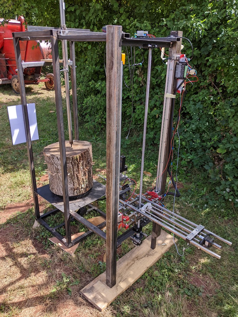
The overall view of M-Bot during a live demo.
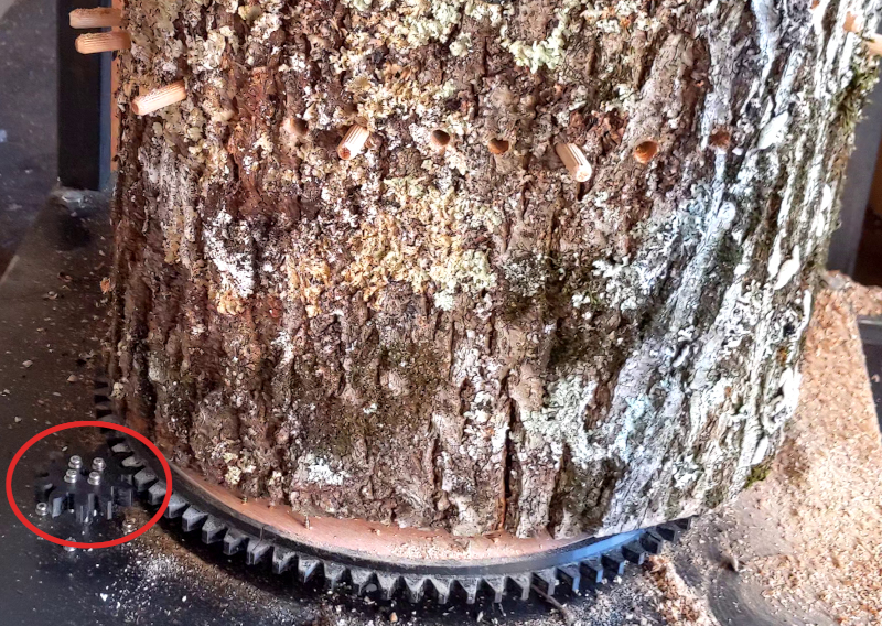
The log is loaded onto the machine, clamped and held in place from the top. The platform rotates thanks to a stepper motor linked through a flange to a 3D printed gear which drives the gear of the platform.
The X axis of M-Bot, on the bottom left of the picture you can see the drive gear.
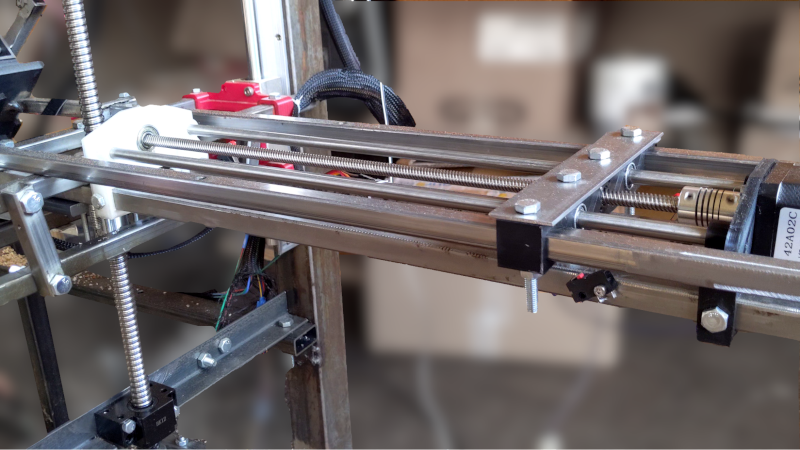
The Y axis is moved with a nema 23 stepper motor coupled to a ball screw (SFU1204, with BK12 and BF12), and is held by linear rails. The Z Axis is similar but the stepper motor is smaller, and it uses linear bearings and an ACME threaded rod.
The Y and Z axis of M-Bot.
I’ve built M-Bot frames using mild steel tubes. Being able to easily procure and weld the frame using a MIG welder was a great benefit to me. I ended up bolting most of the robot using M8x50 and M6x30, in order to more easily disassemble and change parts.
I have spent a lot of time designing hardware around what I had instead of buying specialised parts. I wanted to avoid having multiple bolt lengths and sizes to make assembly quicker and more reliable, but lost a lot of time due to that.
Learnings : The hard part was finding the name of the hardware I needed; what existed and what didn’t. I spent a lot of time making mechanical parts which underperformed compared to what I could’ve bought. Europe is also sadly lacking in cheap and reliable manufacturers such as sendcutsend (there is a 10x price difference between the US and the EU). There also isn’t a distributor like Mc-Mater Carr with well organised hardware (I wish RS-Components was better). In hindsight I should have invested in a lathe and mill, given the time I had to spend on the mechanical side, these tools would have been worth it.
Toolhead
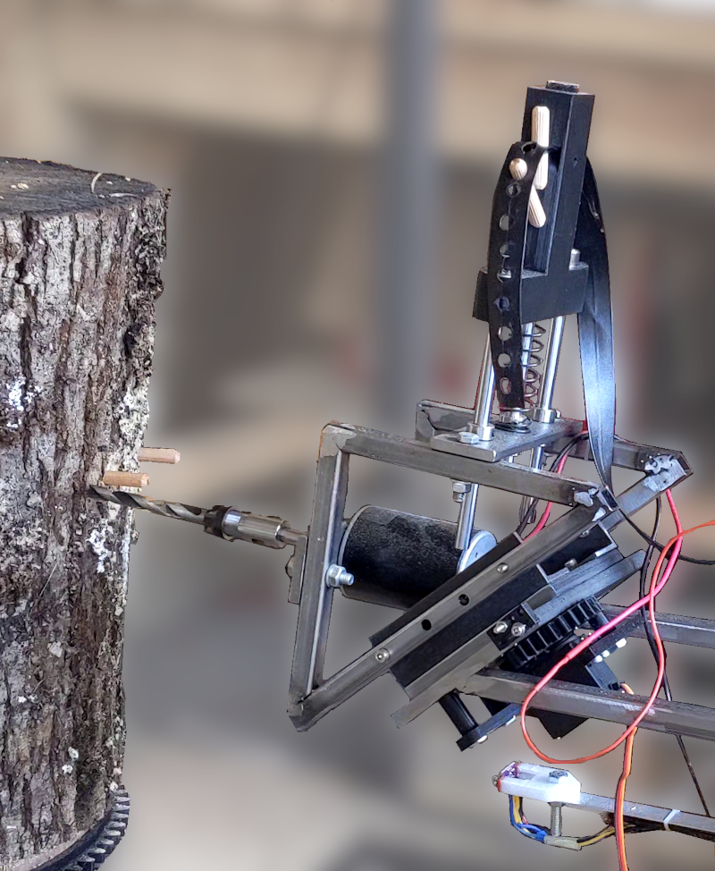
The most complex mechanical part I invented is the toolhead. It holds the drill and the dowel inserter, it switches from one to the other. One plate is welded to the Z axis at a 45 degrees angle, and the other plate rotates against it using a central shaft. A servo motor controls a set of gears that rotate the shaft and either aligns the drill or the inserter.
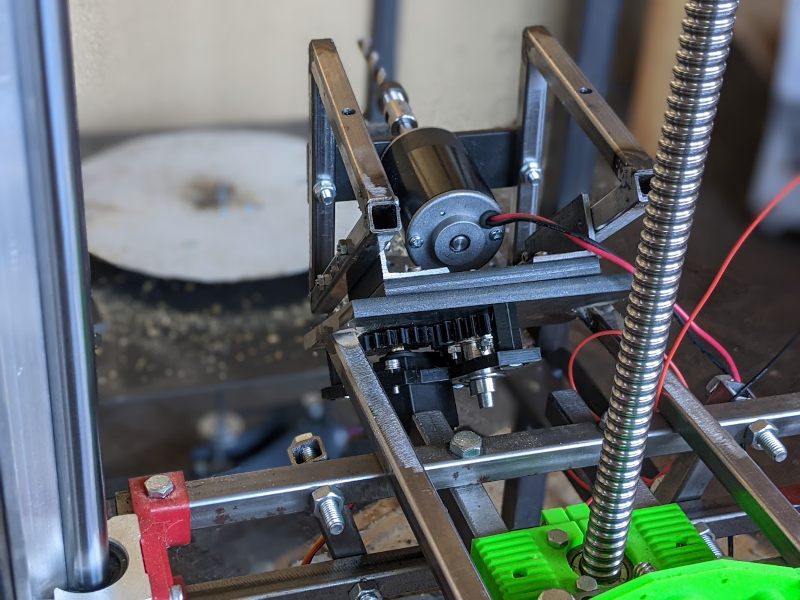
The toolhead drilling a hole.
The inserter pushes a dowel in the piece of wood. It is spring loaded so that the push rod can push the dowel using the Z axis of the CNC and can then return to its initial position.
The difficulty of manufacturing the toolhead came due to the number of parts and the precision required between them. A better design may have been to use the principle used on the lumen pnp, where a linear action swaps one tool with the other. It would have given a base for a mechanism to refill the dowels, and improved the repeatability of the process. However manufacturing this without a mill would have relied on 3D printed parts which may have broken due to the forces exposed. The main reason for the current design was to direct the force directly on the Z axis through the central shaft.
Another issue in the design is that the servo motor isn’t strong enough to perfectly position itself and with the overall play in the gears and plate shaft linkage made it impossible to accurately position the tools. I added mechanical end stops to alleviate this issue, but setting them correctly is extremely hard.
Learnings : this iteration of the toolhead still has many flaws which could have been altered during the design phase. I should have done more tests and research to develop a toolhead. My stubbornness to use a servo motor caused many issues and iterations, bolting a nema 17 stepper motor and using its shaft and bearings would have been simpler and more effective for a proof of concept. I believe that my lack of manufacturing capabilities made that part of the project quite a bit more complicated.
Power supply
I wanted to power the robot with a 12V battery, but when I received the brushed DC motor to use as a drill, it became apparent that it wouldn't provide enough torque at that voltage. Given the relation between torque and voltage, i.e : higher voltage equals higher current equals higher magnetic field equals higher torque, I had to change the input voltage to 24V, which is a standard for tractor batteries.
I had to lower the input voltage for each component. The NEMA 23 used for the Y axis can go up to 48V so I could simply wire it to the input voltage, same as the drill. The NEMA 17 for the X and Z axis can go up to 12V, so I used an external buck converter to lower the voltage. The Servo required 5V and got its own buck converter to isolate it from the rest. The micro controllers were provided with 5V and have their own LDOs for a 3V3 rail, and the TOF sensor works with 1V8 LDO and was plugged to the 3V3 of a microcontroller.
All these voltage rails have different current requirements, and while the size of the step down converters were sized appropriately, the decoupling capacitors were not. It took a lot of debugging to understand the communication issues were caused by a wavering power supply. I added big aluminium electrolytic capacitors on each rail to help alleviate this issue.
On the first revision, I also made the mistake of not calculating the current requirement of the 12V rail, it required up to 8A, and the circuitry I made was only able to supply 2A before thermal shutdown. That is why I used an external step down converter with 10A output.
Learnings : in future prototypes, I’ll try to provide power through external power supply so I do not need to design my board around buck converters and LDOs. Powering the board externally with different rails may be more hassle but it also requires less engineering time, as it is easier to change a single component and its supply instead of redesigning the complete board.
How I changed my CNC shield 12V input to take power from the onboard buck converter or from the external buck converter.
CNC Shield
In order to “simplify” the engineering of the system, I decided early on to use an existing CNC control system. The simplest one I was able to find, used on many cheap 3D printers and other CNC machines, is called GRBL. I designed my board to use that firmware and run it from an Arduino Nano. My reasoning was that smart people already made a system to control 3 axis robot positions through G-Code, and I simply had to give it commands through UART. I’ll comment more about my mistakes on this part in the section about the firmware.
In retrospect, it would have been cheaper for me to buy a complete CNC shield and modify it to my purpose rather than designing my own. A complete CNC shield can be found for 30 euros online. To be fair this allowed me to simplify the overall design and have a much better understanding of that subsystem, so I do not know whether I made a good or bad decision in this case.
Control System
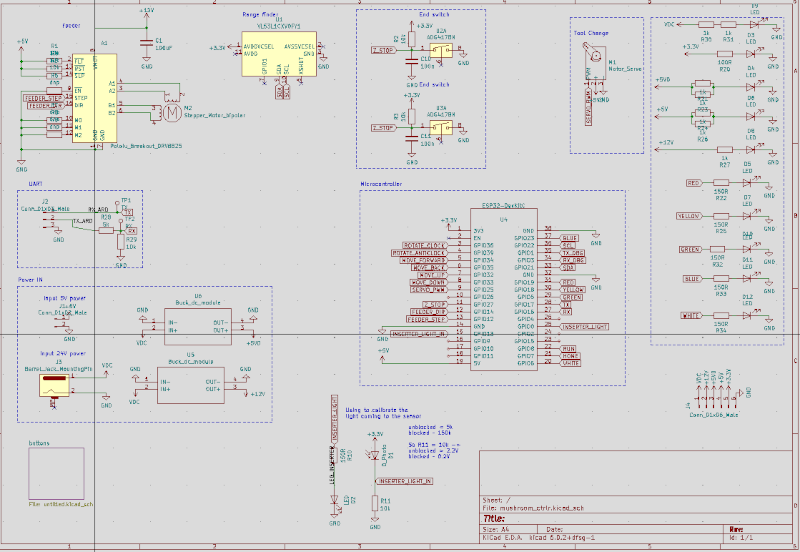
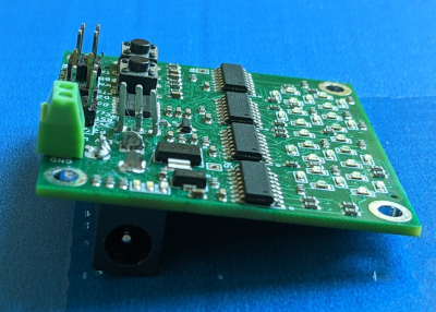
While the positioning was handled by the CNC board, the logic of where and how to positionate the robot was handled by another board. That board has an ESP-32 as a microcontroller, and it connects to the sensors, servo motor, buttons, etc..
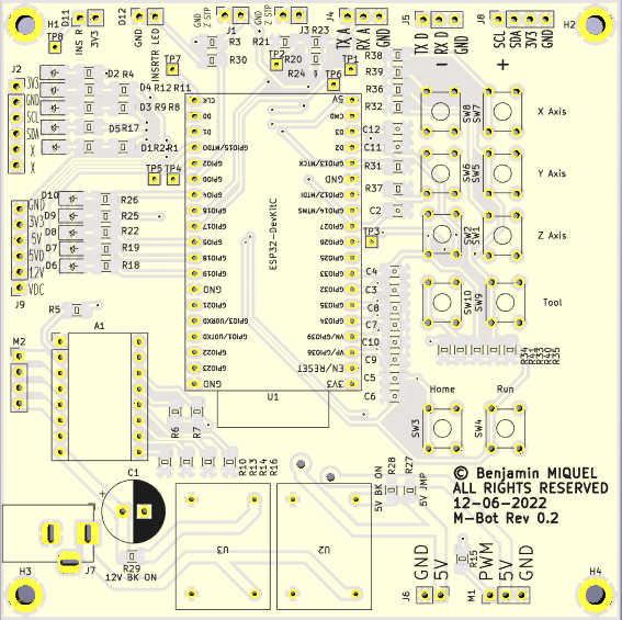
M-Bot Controller board.
I used 1206 components, that is 1.2mm by 0.6mm, as I didn’t want to waste too much time on assembly fiddling with tiny components but didn’t want to use through hole components as it would look amateurish. I used a 100x100mm board with two copper layers.
This design has a few flaws, but my choice of microcontroller is the biggest one, I would have much preferred using an STM32 for example, like on other of my boards. I had decided to use an ESP-32 as I could very easily re-use open source libraries for sensors and save time on firmware design, also I needed 2 UART, one i2c, one PWM, and plenty of GPIOS for the buttons and LEDs. This would also make it very easy to create an UDP server to listen to commands from a computer. Given these requirements, on paper this was a great choice, and during testing on a breadboard every feature worked.
My main issue with that board was that I added decoupling capacitors with a higher capacitance (100nf) than tested; this created issues with the initialization of the bootloader as some SPI communication needs to happen to select the firmware. Removing the capacitors fixed this issue, however, the buttons were no longer working properly as the capacitors were there to remove the noise from these inputs.
I also had some issues with the buttons, and I am not entirely sure why I missed it during testing. Some pins couldn’t be in input pull-down mode, and had to be in pull-ups, but the circuitry didn’t allow this change without annoying re-work. I ended up writing some software to “fix” all of these issues in the end.
Connectors
I mostly used JST-XH connectors for my boards, this made the layout easy as I could put the connectors all around the board, and the crimping was relatively easy once I got used to it. The ones I used are the standard 0.1” or 2.54mm spacing.
Next time I’m making a board I’ll follow the Eurocard standard, and use DIN41612 connectors. It would make finding an enclosure and sub-racks easier. Having one single big connector also has the advantage that it’s easy to connect and disconnect the wiring loom. In my case, as this is a prototype and things had to change during the integration process, like using a test point (TP3) to control the TOF sensor shut-down in order to reset it, it was ok to have a less than optimal board.
I used barrel connectors to carry power, as I had bought a stock in advance, they are easy to plug and unplug. They are also able to carry many amps. I used a big Emergency Stop button thinking that it would be good to have when the robot eventually became sentient and decided to take over the lab. I used that switch many times, when things were stuck, or caught fire.
The wiring loom took quite a few days to make, cut and crimp, most wires are within snake skins, and so won’t get entangled. I’m missing a system with brackets to hold the wires on the robot. I thought this wasn’t a priority, as it didn’t add value to the prototype.
Firmware
I’ve a lot of experience writing software and firmware, so this part was less troublesome. The tough part was to communicate to GRBL through UART to get the status and positions of the CNC machine, but this was manageable with some string parsing in C.
My main issue with GRBL is that it is not possible to reset the alarm (with $X) in a hard fault mode, which happens when hitting a limit switch. I thought of simply modifying the GRBL firmware to allow me to do so, and running that custom firmware. But my quick and dirty solution was to add another switch to reposition the toolhead when the stepper motor lost steps.
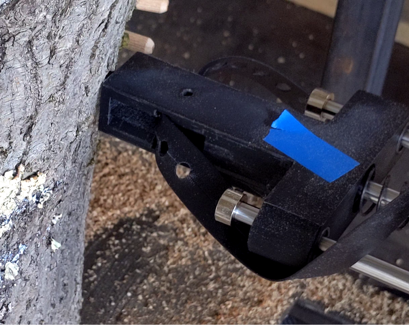
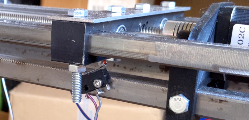
Second Z end switch, being hit before the main Z Stop.
That switch allowed the Z axis to reposition itself every time a dowel was inserted, this is necessary because the stepper motor loses its position when it is no longer able to push the dowel.
The process of inserting a dowel starts by measuring the distance to the log, this is done through the Time Of Flight sensor (TOF), then the drill position itself to just touch the log. It then starts the drill and pecks in the log, 2cm in, 2cm out then 4cm in, at different speeds when going in and going out.
Learning : what I would have improved, is to measure the current going to the DC motor using a fixed gain op amp current sense. This would allow the software to regulate the speed at which to advance into the piece of wood to keep a constant current regardless of the toughness of the piece of wood, i.e. : slower if it is hard, faster if it is soft.
Once the hole has been drilled the toolhead backs off and the firmware slowly changes the servo motor PWM signal in order to slowly turn it to the inserter, if that is not done slowly the servo goes full speed and can’t stop in time due to the mass it carries, the acceleration needs to be controlled.
The Z axis advances and another dowel is inserted in the log, and voilà, the firmware advances the X axis, rotating the log and repeats the process from the start.
I tested more features in order to automate more parts of the system, but I didn’t implement them on the robot for lack of time. Detecting the dowel in the inserter was done with an LED and a light detector. The light detector was first calibrated and then the system was able to see if the dowel had been successfully inserted or not.
I also intended to measure the log using the TOF sensor and rotating it. It would have been able to measure the circumference this way, and know how many dowels to insert.
Conclusion
The goal of this project was to get experience building prototypes, and this certainly achieved that purpose. I’ve spent hundreds of hours fabricating, doing CAD, designing PCBs, and learned a lot about mechanical and electrical components by testing many designs.
M-Bot works. Sure it’s not amazing, but I never intended to make something amazing, don’t let perfection be the enemy of good. At times I had many doubts whether I would ever get M-Bot working at all. I’m very happy to have managed that much. I’m done with M-Bot for now, and I don’t intend to improve it more, I’ll simply show it around.
What does this mean for the future? I’m now looking for projects which are more in my area of expertise, meaning software, firmware and electronics, where the mechanical parts can be bought off the shelf, not complicated to make or are not critical to the project.
In order to find cool projects to work on, I plan to chat with people about their work, their industry and their needs. I’ll simply look at how things can be improved using the expertise I’ve built across the years.
Cleaning up i2c signals
An update on the progress of M-Bot !
I'm working on debugging the issues I've the PCB I've designed.
My main and last issue I've spent the last week debugging concerns the Time Of
Flight sensor, that measures the distance between the piece of work and the
drill.
That sensor has been working flawlessly in my previous test on the breadboard
when I was preparing the firmware. But when plugged to my PCB it didn't work.
Looking at the lines with the Oscilloscope. It's very noisy.
Also the 3.3V power supply to the sensor is pretty noisy, and I thought this was
the main culprit.
Where does the noise come from
My first step was to figure out where the noise came from, and the answer there
is pretty straight forward, the multiple step down buck converters.
Currently M-Bot is plugged to a 230V AC to 24V DC power supply. And that 24V
goes to a 24V-5V buck converter for the Microcontroller which an LDO regulates
to 3V3.
First solution
So I thought the easy way to remove the noise was to remove the power supply,
and use a cleaner source for the microcontrollers. So I checked if this
worked, you know, in case I'm wrong, which never happens.
So it almost worked, but isolation wasn't feasible entirely, even though I could
remove the power supply I needed to share the Ground reference for my UART
lines. And that's where the issue came from. The noisy ground due to all the
inductances on the circuit interfered with my i2c line.
I'm telling this now that I've figured it out, but this took many frustrating
days of debugging.
Can I decouple the Grounds ?
Not really without a lot of rework. I would need to set octo-coupler, and used
transceivers for the UART communication (instead of my janky voltage divider).
But in the future I'll keep this in mind. Decoupling between the power system
and the signal is good practice.
Final solution
After trying many things, I've found out that decreasing the clock speed and
using big electrolitic capacitors on the power lines removed a lot of my noise.
I also added another line, soldered to a GPIO to reset the sensor when it was
not working properly. Something that I think I should do in the future for all
sensors.
I made the firmware try to reset the sensor in multiple ways, in order to
re-initialized I figured out it crashed.
I also though of putting an 3V3 LDO dedicated and near the sensor, in order to
remove the VCC noise.
Reflowing Boards for M-Bot
PCB assembly at home
I've been away in Munich working on many things including assembly of PCBs. This
was perfect as I had to assemble new boards for M-Bot.
I've re-made the CNC controller board in order to correct a few mistakes I made
the last time, also I designed the controller board around an ESP32.
Here you see me reflowing manually some components. I don't have any fancy
infrared reflowing oven, but I made it work regardless.
Also, these are big components 1206, which is 1.2mm long and 0.6mm wide. That
may seem tiny, but in comparison with 0603 which are half the size, a quarter
of the area and a eighth of the volume, these are big boys !
I didn't get a stencil for my boards and used a big syringe, and I wouldn't want
to do this with components smaller than 0805, and while the cost of a stencil
isn't huge, I don't think it's very necessary to assemble 30 components.
Automating
There are two ways to automate the assembly of PCB.
You get a contract manufacturer to do it for you
You use machines to pick and place components
The first option is something I've used for my other project, as assembling 3000
components (over 10 boards) is not fun for long. Though it takes a lot of
planning to ensure that you operate within the manufacturer's capabilities.
I'm looking at the second option as this is something I would love to set up in
my own capabilities. Being able to assemble small amounts of boards and creating a
JIT (Just In Time) manufacturing process to manufacture boards on demand at a
smaller cost than contract manufacturers in Europe can do, but more rapidly than
importing from Asia.
There is this Lumen PNP project which
is relatively new, launched only a few months ago; I think it has some good
potential to compete on the low scale. I am thinking of setting this up, though
I would still need some PCB to populate, i.e. a reason to do so, maybe my solar
clock is something I can make with ?
Q2 Update
Dear readers, it’s time for another update !
Since last time, I’ve focused on two projects, the LED strip controller and of course M-Bot. My high-level update is that I’ve made a new version of the LED strip controller which still needs to be tested and programmed, and M-Bot is now alive and kicking, though is still missing its head.
LED strip controller
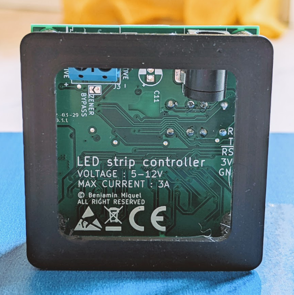
I’ve fully redesigned the board with some advice from an electronics engineer. The main things I wanted to add were safety features, as users will always find a way to make mistakes. I’ve added an over voltage protection in case someone plugs 24V instead of 12V, a reverse voltage protection in case someone plugs it backward, and overcurrent protection in the form of a fuse that will blow up if something goes wrong, and it is sadly not resettable at the moment. (First picture is v1, second picture is v2)
I also changed the MOSFET from a P channel to a N channel; they both function in similar and yet different ways, they both act as gates that are set ON and OFF by setting the gate voltage. P channels are before the load and N channels are after. They have different “chemistry” which makes the N channel more efficient [Rds(On)], so they heat up less. In my case I calculated more than 100 degrees of temperature rise for a P-FET, and 30 for a N-FET, this means the components can be smaller and cheaper.
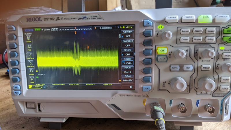
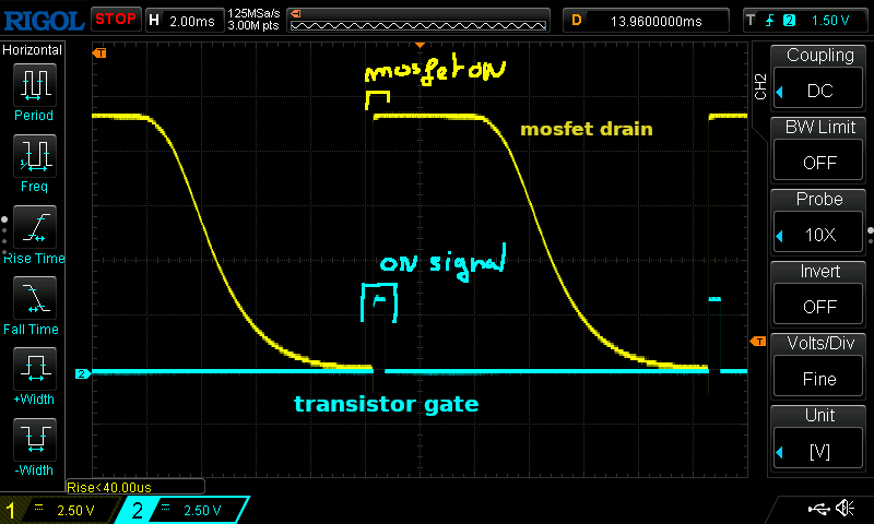
While testing I’ve found an issue that the LED Strip requires some time to switch off, because of that I’ve recently invested in an oscilloscope to debug electrical issues.
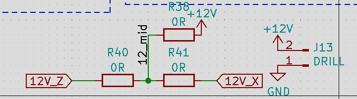
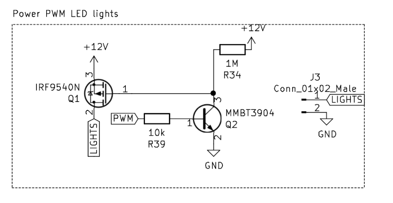
Above is a screen capture from the oscilloscope, the ON time of the transistor gate is tiny (blue) which sets the MOSFET gate low powering the strip (yellow) by letting the current through. But it takes a long time for the MOSFET voltage to drop back to 0V.
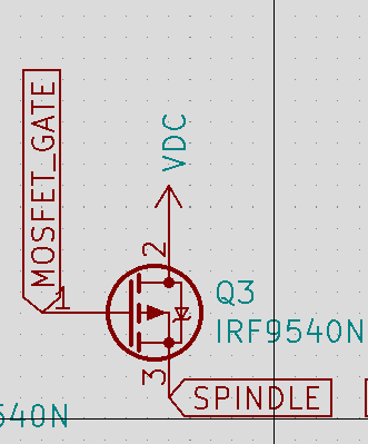
Here is the schematics, and the reason we can see this behaviour is most likely due to R34 value, 1MΩ, a value of 10-20kΩ is probably more appropriate here, so the gate reverts back to 12V faster and blocks the current flow.
I’ve looked into manufacturing these devices and went through the EU regulation to understand what is needed, and wrote an article on my blog, you can skip the next part if you already read it.
I need to engineer a product compliant with all the regulations to be able to sell it in the EU, and the EU wrote multiple “harmonisation” documents for products. The regulations explain things such as : a power supply needs to have minimum efficiency while powering or not powering something, the goal of that regulation is to save energy on things plugged to the wall that don't do anything.
It’s not too burdensome to actually apply these regulations, they are well written and to the point. However you need to find all the regulations that may apply to your product, and argue why some are or aren’t relevant to your application. So going through the definitions and exceptions of every Harmonised Standard.
(CE symbol stating the compliance with EU regulations)
Once you’ve engineered that device you need to write a bunch of documentation and keep it for 10 years as the manufacturer. I’ve not found an example of what is required or standards to follow, so it’s pretty broad.
Then, time to manufacture your product in compliance and keep track / record of how you complied with the regulation.
For EEE products, the main regulation is ROHS, which regulates harmful substances within an electrical appliance, things like lead or cadmium.
Also you need to be part of a WEEE group, which is a recycling chain, you need to have a contract with as a seller of EEE goods.
(WEEE Symbol requiring the product to recycled)
This is to me the most annoying part, as it requires working with private for profit entities. You also need to report TONS of products put on the market to the government, which is actually a simple process. The fact that you need to report tons of products really shows the barrier of entry of a seller of electronics goods in the EU. Also every member state (MS) is different and you need to sign a contract for every country and report the tons of product put on the market for each MS, so it makes it quite expensive to sell your product across borders.
Also, take what I wrote with some salt, I am no expert, and I also skipped many details in order to write something as concise as I can.
M-Bot
M-Bot is now fully sentient and intends to take over the world, thankfully it is not yet very coordinated. It is moving, all axes are functional, even though it’s still quite brain dead.
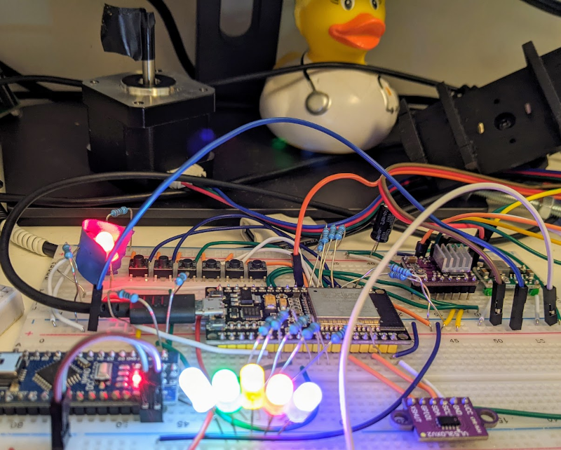
(This is M-Bot’s brain, with a servo and a stepper motor, sensors and LEDs. I am doing brain surgery instead of finishing this newsletter !)
I’ve worked on the nervous system (i.e. : the electrical system) till now, and just started to program the main microcontroller.
On the mechanical side. The tool head; the most complicated part of the robot; has been made. I had many issues, and it took many weeks to machine and to build. A true learning experience. The main point I am taking away from this project is that some parts are better bought than built.
You can learn a lot from making parts and many have to be made, but some are easy to buy, and this is something I learned the hard way. For example, to hold my 8mm shaft, I used a nut which I drilled the thread from, and drilled a 2.5 mm hole which tapped with an M3 tap. This took hours to do, and broke many drill bits (and taps). Parts which you can buy for 1 euro each with shipping and next day delivery.
(Aforementioned parts called “Serrure à vis mère” not sure what is their english name)
Mechanical parts often seem easy to make, however the accuracy often necessary to make them is hard to achieve for me in my shop without a mill or lathe. It can take multiple hours to drill 6 holes into 3.5mm thick steel. Making the holes concentric with other parts, in the right position and with the right tolerances; it is so much easier in theory than in practice.
In the future I am pretty sure I need to find someone to work the mechanical side with me, someone with a lathe, a mill, and the dozen of other tools required to make them work. This is something that cannot be improvised or done quickly.
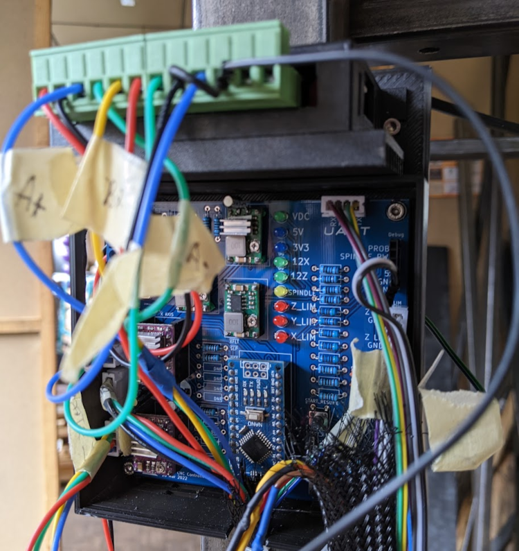
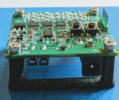
(The CNC Controller board I made for managing the tool head location in 3D space)
On the electrical side I’ve wired all the switches and motors, and discovered I had some thermal issues which triggered the thermal cutoff switch in the IC, and burned my fingies with the hot hot ICs. I’ve temporarily solved the issue by under powering the motors, and stuck some heat sinks on them. The issue is due to my buck converters, which are quite underpowered. I did use 3 of them (green bits next to the LEDs), one for each part of the circuitry to try to alleviate this effect. I’ll likely redesign this part of the circuit with my own step down power supply, or simply use an external buck converter.
(close up on the P Mosfet)
I had a small issue with my MOSFET, if you look closely at the schematics it’s plugged in reverse, so the motor is always on. You can see below the zener diode (-⊳≀-) points towards the SPINDLE (i.e. : bottom), so the gate doesn’t do anything, and let the current through. This was solved through “skilled” wiring, and bending of the TO-220 package to fit the requirement.
(Some parts of the schematics for controlling M-Bot that can be seen on the breadboard)
Next steps for M-Bot is to fully test the robot, replace everything that doesn’t work, create something to hold the piece of wood, design and order a custom PCB for the micro-controller. Quite a bit of work to complete the prototype, but I’ll soon be able to try it out ! Right now I’m doing the software for each part, and testing the electronics so I can design the PCB.
Conclusion
It feels like I’ve been less productive this time, I am not sure if this was actually the case or this is because I ran into harder issues to solve. Hopefully I’ll finish one of these projects soon, so I can showcase it.
I’ll soon be back in Munich working with the start-up on firmware, test benches, electronics, and CAD designs, so doing what I enjoy with people I enjoy being around, personal projects will take a bit of a break, though I usually find the time to order parts, and do some work I postponed.
Fox ears, or my bird network project is on hold. I ran into a firmware issue where the microprocessor doesn't have enough RAM to process enough FFT, and the triggering accuracy is pretty bad. Also, I decided to focus my time on the project I can realistically finish and that one is too much for me alone in the time I have.
I hope you’ve enjoyed reading this newsletter, and you were entertained by my work. It is tough to decide on what is worth writing on and what is not. So let me know if there is something I should write more about.
 Welcome on blog.benjamin-miquel.fr - Subscribe to the newsletter : newsletter.benjamin-miquel.fr

 (CE symbol stating the compliance with EU regulations)
 (WEEE Symbol requiring the product to recycled)