When showcasing my robot, the question everyone asked was “what is it doing ?”. So here is some context on how mushrooms grow.
Mushrooms you buy in the store are the fruits of a fungus. A fungus is composed of small interconnected tubes that feed on biomass, called mycelium.
The simplest way to cultivate mushrooms is to take biomass and inoculate (i.e. : plant) it with mycelium. Wait a few months for the fungus to feed and then mushrooms will sprout.
In my case, I want to cultivate shiitake; they feed on wood, and it is a relatively easy mushroom to cultivate. The first step is to start by cutting down a tree in 1m long logs, then drilling holes in a 15cm grid pattern, finally inserting around 50 dowels in those holes that contain the mycelium, the mycelium will then spread and eat the log.
The robot's purpose is to automate the drilling and dowel inserting process.
The main industrial process today to cultivate mushrooms in bulk is using large amounts of biomass, such as compost, hay, and wood chips. Inoculating the biomass and keeping the humidity and temperature controlled to optimise the growth.
On the smaller scale, a chainsaw, drill and hammer can lead to the same result, though it requires more manual labour. Leaving the logs in the forest where they can be harvested when they reach maturity.
This robot niche is in the middle, processing logs faster without the investment required for a complete factory.
My goal was to create a minimal viable product, to build some practical experience building prototypes. I have no intention of selling a product given the investment required to have a well performing tool, designing it for manufacturing (DFM), complying with the EU Harmonised Standards (LVD, RoHS, MD), managing investments, sales and all the complexities of running a company.
After this project I wanted the ability to judge what type of project to take on, depending on the technologies, scope, industry, and manufacturing requirements in question.
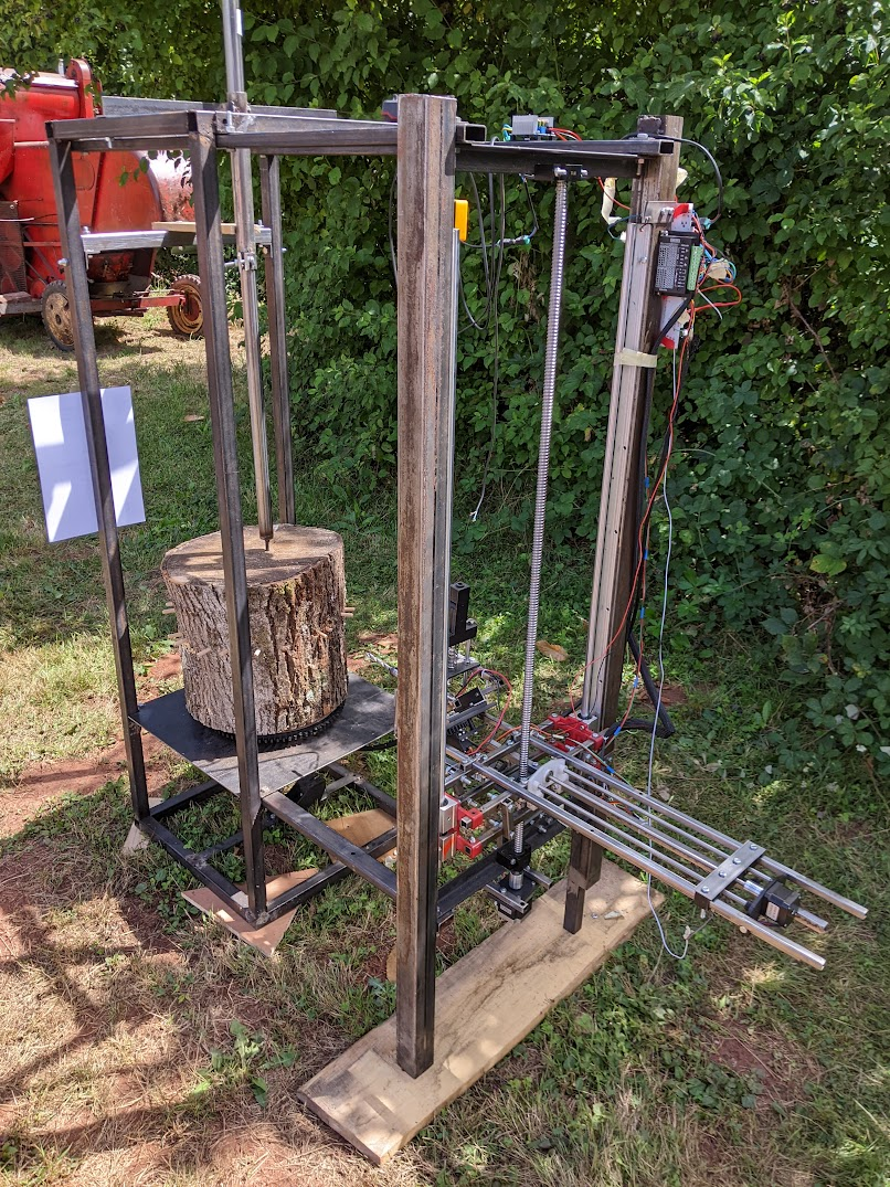
My robot works in a similar way to a CNC mill with a rotary table. The log is loaded on a rotating platform which corresponds to the X axis. A toolhead is moved vertically on the Y axis and it advances horizontally on the Z axis.
The overall view of M-Bot during a live demo.
The log is loaded onto the machine, clamped and held in place from the top. The platform rotates thanks to a stepper motor linked through a flange to a 3D printed gear which drives the gear of the platform.
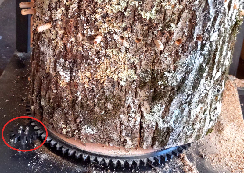
The X axis of M-Bot, on the bottom left of the picture you can see the drive gear.
The Y axis is moved with a nema 23 stepper motor coupled to a ball screw (SFU1204, with BK12 and BF12), and is held by linear rails. The Z Axis is similar but the stepper motor is smaller, and it uses linear bearings and an ACME threaded rod.
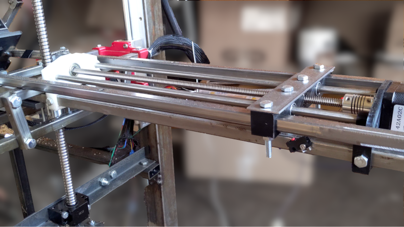
The Y and Z axis of M-Bot.
I’ve built M-Bot frames using mild steel tubes. Being able to easily procure and weld the frame using a MIG welder was a great benefit to me. I ended up bolting most of the robot using M8x50 and M6x30, in order to more easily disassemble and change parts.
I have spent a lot of time designing hardware around what I had instead of buying specialised parts. I wanted to avoid having multiple bolt lengths and sizes to make assembly quicker and more reliable, but lost a lot of time due to that.
Learnings : The hard part was finding the name of the hardware I needed; what existed and what didn’t. I spent a lot of time making mechanical parts which underperformed compared to what I could’ve bought. Europe is also sadly lacking in cheap and reliable manufacturers such as sendcutsend (there is a 10x price difference between the US and the EU). There also isn’t a distributor like Mc-Mater Carr with well organised hardware (I wish RS-Components was better). In hindsight I should have invested in a lathe and mill, given the time I had to spend on the mechanical side, these tools would have been worth it.
The most complex mechanical part I invented is the toolhead. It holds the drill and the dowel inserter, it switches from one to the other. One plate is welded to the Z axis at a 45 degrees angle, and the other plate rotates against it using a central shaft. A servo motor controls a set of gears that rotate the shaft and either aligns the drill or the inserter.
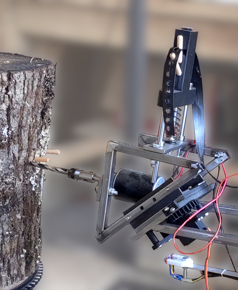
The toolhead drilling a hole.
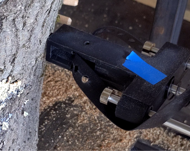
The inserter pushes a dowel in the piece of wood. It is spring loaded so that the push rod can push the dowel using the Z axis of the CNC and can then return to its initial position.
The difficulty of manufacturing the toolhead came due to the number of parts and the precision required between them. A better design may have been to use the principle used on the lumen pnp, where a linear action swaps one tool with the other. It would have given a base for a mechanism to refill the dowels, and improved the repeatability of the process. However manufacturing this without a mill would have relied on 3D printed parts which may have broken due to the forces exposed. The main reason for the current design was to direct the force directly on the Z axis through the central shaft.
Another issue in the design is that the servo motor isn’t strong enough to perfectly position itself and with the overall play in the gears and plate shaft linkage made it impossible to accurately position the tools. I added mechanical end stops to alleviate this issue, but setting them correctly is extremely hard.
Learnings : this iteration of the toolhead still has many flaws which could have been altered during the design phase. I should have done more tests and research to develop a toolhead. My stubbornness to use a servo motor caused many issues and iterations, bolting a nema 17 stepper motor and using its shaft and bearings would have been simpler and more effective for a proof of concept. I believe that my lack of manufacturing capabilities made that part of the project quite a bit more complicated.
I wanted to power the robot with a 12V battery, but when I received the brushed DC motor to use as a drill, it became apparent that it wouldn't provide enough torque at that voltage. Given the relation between torque and voltage, i.e : higher voltage equals higher current equals higher magnetic field equals higher torque, I had to change the input voltage to 24V, which is a standard for tractor batteries.
I had to lower the input voltage for each component. The NEMA 23 used for the Y axis can go up to 48V so I could simply wire it to the input voltage, same as the drill. The NEMA 17 for the X and Z axis can go up to 12V, so I used an external buck converter to lower the voltage. The Servo required 5V and got its own buck converter to isolate it from the rest. The micro controllers were provided with 5V and have their own LDOs for a 3V3 rail, and the TOF sensor works with 1V8 LDO and was plugged to the 3V3 of a microcontroller.
All these voltage rails have different current requirements, and while the size of the step down converters were sized appropriately, the decoupling capacitors were not. It took a lot of debugging to understand the communication issues were caused by a wavering power supply. I added big aluminium electrolytic capacitors on each rail to help alleviate this issue.
On the first revision, I also made the mistake of not calculating the current requirement of the 12V rail, it required up to 8A, and the circuitry I made was only able to supply 2A before thermal shutdown. That is why I used an external step down converter with 10A output.
Learnings : in future prototypes, I’ll try to provide power through external power supply so I do not need to design my board around buck converters and LDOs. Powering the board externally with different rails may be more hassle but it also requires less engineering time, as it is easier to change a single component and its supply instead of redesigning the complete board.
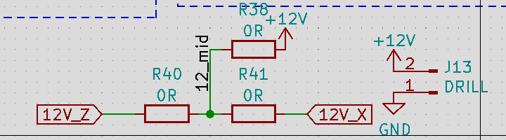
How I changed my CNC shield 12V input to take power from the onboard buck converter or from the external buck converter.
CNC Shield
In order to “simplify” the engineering of the system, I decided early on to use an existing CNC control system. The simplest one I was able to find, used on many cheap 3D printers and other CNC machines, is called GRBL. I designed my board to use that firmware and run it from an Arduino Nano. My reasoning was that smart people already made a system to control 3 axis robot positions through G-Code, and I simply had to give it commands through UART. I’ll comment more about my mistakes on this part in the section about the firmware.
In retrospect, it would have been cheaper for me to buy a complete CNC shield and modify it to my purpose rather than designing my own. A complete CNC shield can be found for 30 euros online. To be fair this allowed me to simplify the overall design and have a much better understanding of that subsystem, so I do not know whether I made a good or bad decision in this case.
While the positioning was handled by the CNC board, the logic of where and how to positionate the robot was handled by another board. That board has an ESP-32 as a microcontroller, and it connects to the sensors, servo motor, buttons, etc..
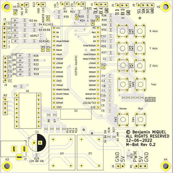
M-Bot Controller board.
I used 1206 components, that is 1.2mm by 0.6mm, as I didn’t want to waste too much time on assembly fiddling with tiny components but didn’t want to use through hole components as it would look amateurish. I used a 100x100mm board with two copper layers.
This design has a few flaws, but my choice of microcontroller is the biggest one, I would have much preferred using an STM32 for example, like on other of my boards. I had decided to use an ESP-32 as I could very easily re-use open source libraries for sensors and save time on firmware design, also I needed 2 UART, one i2c, one PWM, and plenty of GPIOS for the buttons and LEDs. This would also make it very easy to create an UDP server to listen to commands from a computer. Given these requirements, on paper this was a great choice, and during testing on a breadboard every feature worked.
My main issue with that board was that I added decoupling capacitors with a higher capacitance (100nf) than tested; this created issues with the initialization of the bootloader as some SPI communication needs to happen to select the firmware. Removing the capacitors fixed this issue, however, the buttons were no longer working properly as the capacitors were there to remove the noise from these inputs.
I also had some issues with the buttons, and I am not entirely sure why I missed it during testing. Some pins couldn’t be in input pull-down mode, and had to be in pull-ups, but the circuitry didn’t allow this change without annoying re-work. I ended up writing some software to “fix” all of these issues in the end.
Connectors
I mostly used JST-XH connectors for my boards, this made the layout easy as I could put the connectors all around the board, and the crimping was relatively easy once I got used to it. The ones I used are the standard 0.1” or 2.54mm spacing.
Next time I’m making a board I’ll follow the Eurocard standard, and use DIN41612 connectors. It would make finding an enclosure and sub-racks easier. Having one single big connector also has the advantage that it’s easy to connect and disconnect the wiring loom. In my case, as this is a prototype and things had to change during the integration process, like using a test point (TP3) to control the TOF sensor shut-down in order to reset it, it was ok to have a less than optimal board.
I used barrel connectors to carry power, as I had bought a stock in advance, they are easy to plug and unplug. They are also able to carry many amps. I used a big Emergency Stop button thinking that it would be good to have when the robot eventually became sentient and decided to take over the lab. I used that switch many times, when things were stuck, or caught fire.
The wiring loom took quite a few days to make, cut and crimp, most wires are within snake skins, and so won’t get entangled. I’m missing a system with brackets to hold the wires on the robot. I thought this wasn’t a priority, as it didn’t add value to the prototype.
I’ve a lot of experience writing software and firmware, so this part was less troublesome. The tough part was to communicate to GRBL through UART to get the status and positions of the CNC machine, but this was manageable with some string parsing in C.
My main issue with GRBL is that it is not possible to reset the alarm (with $X) in a hard fault mode, which happens when hitting a limit switch. I thought of simply modifying the GRBL firmware to allow me to do so, and running that custom firmware. But my quick and dirty solution was to add another switch to reposition the toolhead when the stepper motor lost steps.
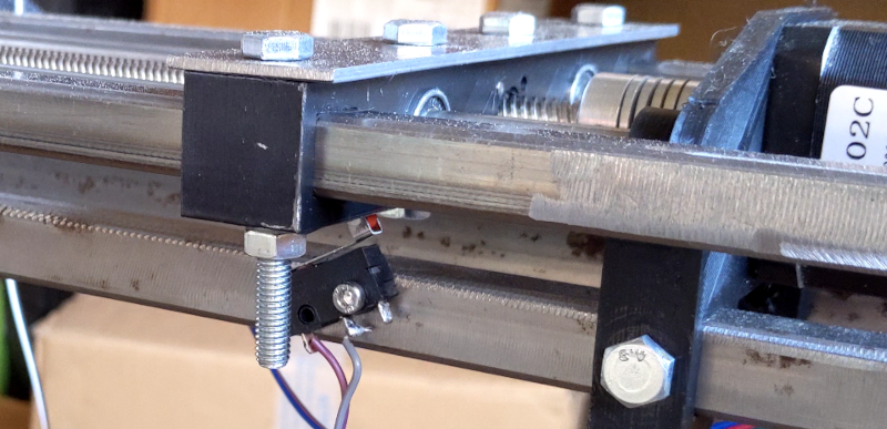
Second Z end switch, being hit before the main Z Stop.
That switch allowed the Z axis to reposition itself every time a dowel was inserted, this is necessary because the stepper motor loses its position when it is no longer able to push the dowel.
The process of inserting a dowel starts by measuring the distance to the log, this is done through the Time Of Flight sensor (TOF), then the drill position itself to just touch the log. It then starts the drill and pecks in the log, 2cm in, 2cm out then 4cm in, at different speeds when going in and going out.
Learning : what I would have improved, is to measure the current going to the DC motor using a fixed gain op amp current sense. This would allow the software to regulate the speed at which to advance into the piece of wood to keep a constant current regardless of the toughness of the piece of wood, i.e. : slower if it is hard, faster if it is soft.
Once the hole has been drilled the toolhead backs off and the firmware slowly changes the servo motor PWM signal in order to slowly turn it to the inserter, if that is not done slowly the servo goes full speed and can’t stop in time due to the mass it carries, the acceleration needs to be controlled.
The Z axis advances and another dowel is inserted in the log, and voilà, the firmware advances the X axis, rotating the log and repeats the process from the start.
I tested more features in order to automate more parts of the system, but I didn’t implement them on the robot for lack of time. Detecting the dowel in the inserter was done with an LED and a light detector. The light detector was first calibrated and then the system was able to see if the dowel had been successfully inserted or not.
I also intended to measure the log using the TOF sensor and rotating it. It would have been able to measure the circumference this way, and know how many dowels to insert.
The goal of this project was to get experience building prototypes, and this certainly achieved that purpose. I’ve spent hundreds of hours fabricating, doing CAD, designing PCBs, and learned a lot about mechanical and electrical components by testing many designs.
M-Bot works. Sure it’s not amazing, but I never intended to make something amazing, don’t let perfection be the enemy of good. At times I had many doubts whether I would ever get M-Bot working at all. I’m very happy to have managed that much. I’m done with M-Bot for now, and I don’t intend to improve it more, I’ll simply show it around.
What does this mean for the future? I’m now looking for projects which are more in my area of expertise, meaning software, firmware and electronics, where the mechanical parts can be bought off the shelf, not complicated to make or are not critical to the project.
In order to find cool projects to work on, I plan to chat with people about their work, their industry and their needs. I’ll simply look at how things can be improved using the expertise I’ve built across the years.