An update on the progress of M-Bot !
I'm working on debugging the issues I've the PCB I've designed.
My main and last issue I've spent the last week debugging concerns the Time Of Flight sensor, that measures the distance between the piece of work and the drill.
That sensor has been working flawlessly in my previous test on the breadboard when I was preparing the firmware. But when plugged to my PCB it didn't work.
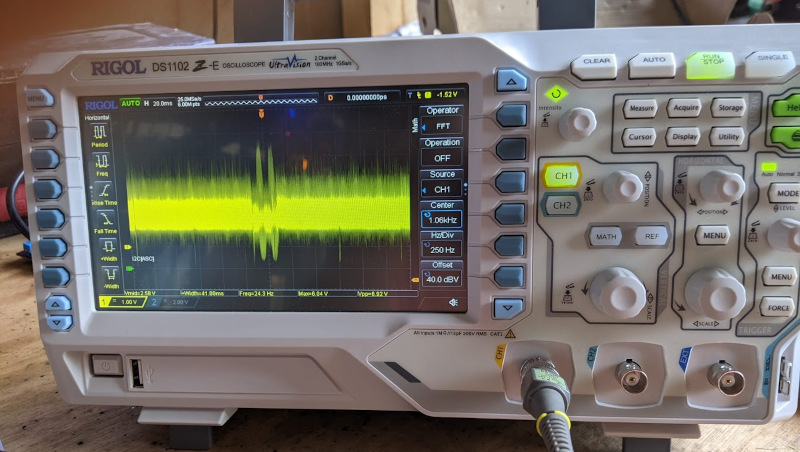
Looking at the lines with the Oscilloscope. It's very noisy.
Also the 3.3V power supply to the sensor is pretty noisy, and I thought this was the main culprit.
My first step was to figure out where the noise came from, and the answer there is pretty straight forward, the multiple step down buck converters.
Currently M-Bot is plugged to a 230V AC to 24V DC power supply. And that 24V goes to a 24V-5V buck converter for the Microcontroller which an LDO regulates to 3V3.
So I thought the easy way to remove the noise was to remove the power supply, and use a cleaner source for the microcontrollers. So I checked if this worked, you know, in case I'm wrong, which never happens.
So it almost worked, but isolation wasn't feasible entirely, even though I could remove the power supply I needed to share the Ground reference for my UART lines. And that's where the issue came from. The noisy ground due to all the inductances on the circuit interfered with my i2c line.
I'm telling this now that I've figured it out, but this took many frustrating days of debugging.
Not really without a lot of rework. I would need to set octo-coupler, and used transceivers for the UART communication (instead of my janky voltage divider). But in the future I'll keep this in mind. Decoupling between the power system and the signal is good practice.
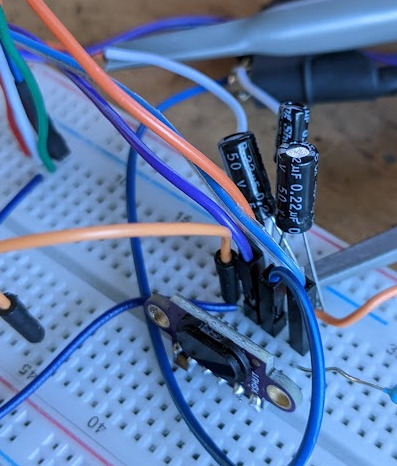
After trying many things, I've found out that decreasing the clock speed and using big electrolitic capacitors on the power lines removed a lot of my noise.
I also added another line, soldered to a GPIO to reset the sensor when it was not working properly. Something that I think I should do in the future for all sensors.
I made the firmware try to reset the sensor in multiple ways, in order to re-initialized I figured out it crashed.
I also though of putting an 3V3 LDO dedicated and near the sensor, in order to remove the VCC noise.